USB to UART serial bridges
USB to UART converters or bridges present themselves as a serial port to your computer and send serial data over a couple of wires. They can be used to make a serial connection to another device. In this post we’ll look into how this works.
Applications
From a hacking perspective, the most interesting application of UARTs is in embedded devices. Most embedded devices have a UART header on the board. The device sends console output and accepts commands over the UART interface. Often, this gives direct access to a root shell.
UART communication is sometimes also needed to interact with a development board, such as an Arduino or ESP8266, although most of these boards have a USB to serial converter on board.
Several other protocols are built upon UART communication, such as IrDA, DMX, MIDI and smart meter P1 ports. These can be used with USB to UART bridges, but require further hacking to get working.
Communicating with UARTs
When two devices communicate using UART, they are connected with at least three wires:
- Common ground, or 0V, or the negative lead of the power supply.
- The transmitting pin (Tx) of one device is connected to the receiving pin (Rx) of the other device.
- Similarly, Rx is connected to Tx.
- For isolated adapters, Vcc or the positive lead of the power supply.
Now, the devices can send data to each other by varying the voltage on the Tx lines, and read data by checking the voltage on the Rx line. UART uses a binary protocol, so there are only two voltage levels: high and low.
There is no clock signal and no negotiation between the two devices. To correctly communicate, both devices must be configured beforehand to use the same speed of communication, called the baud rate.
Baud rate
The baud rate is a term for the number of bits per second that are transmitted over the wire. A common baud rate is 9600 bits per second. In that case, one bit takes up 1∕9600 of a second, or 104µs.
The sending party flips the signal every 104µs, and the receiving party checks the voltage on the line every 104µs. It will still work if this is off by a couple of per cent. This sometimes happens with microcontrollers, that have trouble keeping an exact clock.
The most common baud rates in use are 9600 and 115200. Then there are a handful of standard baud rates, such as 19200 and 38400. In theory you can use any baud rate, but old interfaces only support the standard baud rates. It is possible to use different baud rates for sending and receiving, although this is pretty rare.
Start, stop and parity bits
UART frames consist of a start bit, seven or eight data bits, optionally a parity bit and one or two stop bits. By far the most common configuration is to use eight data bits, no parity bit and one stop bit, or 8N1. So the transmitting party first sends a start bit, then eight data bits, followed by a stop bit.
Voltage levels
UARTs use two voltages: one voltage indicates a 0 bit and another voltage indicates a 1 bit. What voltage exactly is used depends on the device:
- RS232 serial ports use negative and positive voltages, up to -15V and 15V.
- Some devices use 0V and 5V, such as an Arduino Uno that runs on 5V.
- Most devices use 0V and 3.3V.
- Some devices use 0V and 1.8V.
For RS232, negative voltage is a logical 1, positive voltage a 0. For most other UART devices, 0V indicates a 0 bit and the higher voltage indicates a 1 bit.
To avoid frying your device, it is important to use the correct voltage. Connecting your 3.3V bridge to a 15V RS232 line will quickly destroy it.
Voltage that ranges between 0 and power supply voltage (Vcc) is also called TTL voltage levels. 5V TTL voltage levels consider everything above 2V a logic high, and can thus also receive data from 3.3V UART devices. So in that case it is possible to communicate with a 5V UART using a 3.3V UART.
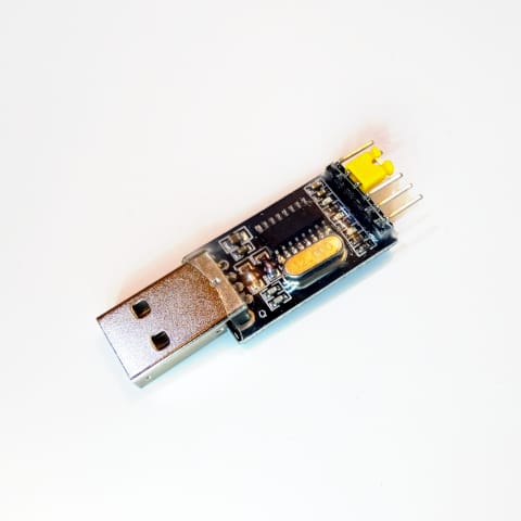
USB to UART converter module
To let your computer talk UART, you need a device that converts computer bytes to UART signals; a USB to UART converter module. This is a small device that plugs into your USB port and has at least ground, Rx and Tx outputs. It pretends to be a serial port to your computer. The computer sends data to this serial port and the module converts it to UART signals.
Chip differences
A USB to UART bridge has a chip on it specifically for this purpose. There are several commonly used chip families:
- Jiangsu Qinheng / WCH CH340
- Silicon Labs CP2102
- Prolific PL2303
- FTDI FT232
These have different versions with different specs:
| Chip | Price | I/O voltage | Max baud rate | Buffer size | GPIO | Datasheet |
|---|---|---|---|---|---|---|
| CH340 | €0.25 | 3.3 / 5V | 2 Mbps | 32 + 32 B | 0 | CH340 |
| CH341 | €0.75 | 3.3 / 5V | 2 Mbps | 32 + 32 B | 0 | CH341 |
| CP2102 | €0.75 | 3.3V1 | 1 Mbps | 576 + 640 B | 0 | CP2102/9 |
| CP2102N | €1.50 | 3.3V | 3 Mbps | 512 + 512 B | 7 | CP2102N |
| PL2303HXD | €0.90 | 1.8 - 3.3V1 | 12 Mbps | 512 B | 4 | PL2303HXD |
| PL2303TA | €0.70 | 1.8 - 3.3V | 6 Mbps | 512 B | 2 | PL2303TA |
| FT232R | €3.50 | 1.8 - 5V | 3 Mbps | 128 + 256 B | 4 | FT232R |
| FT231X | €1.80 | 1.8 - 4V | 3 Mbps | 512 + 512 B | 4 | FT231X |
- The CP2102 and PL2302HXD only output a maximum 3.3V, but can take up to 5V as input, making them compatible with 5V UART devices.
Besides the differences in the chips, the quality of the drivers also differs between the various chips. Some chips have Windows drivers built-in to Windows or distributed through Windows Update, creating a plug-and-play experience. Other chips have drivers that reliably crash the operating system when you read and write significant amounts of data to the device. Linux is an exception in this, since the Linux drivers are written, maintained and checked by kernel developers instead of the chip manufacturer.
The FTDI is around the longest and was previously the only implementation available for USB to UART bridges. They were so common that a bridge was often called a FTDI, after the company name that made the converter chip. Nowadays, they are quickly taken over by much cheaper Chinese converter chips.
Fake FTDI chips
FTDI FT232 chips are pretty popular and relatively expensive (€3.50). This led to the rise of fake Chinese knock-offs. These imitations have the FTDI logo on them and work correctly, and are hard to tell from fakes.
FTDI was not happy with this. In 2014 they pushed a driver update that only works with real FTDI chips, and bricked counterfeit chips. Later they reverted this controversial behavior, but it severely damaged their reputation. Despite that, fake FT232 chips are still widely used and available.
Adapter differences
The cheapest adapters simply have an USB port and pin header directly connected to the chip. They typically expose only ground, positive voltage (Vcc), Rx and Tx, and not other data control modem lines such as RTS and CTS.
There are also galvanically isolated adapters. These use the ground and Vcc of the device you want to communicate with, and don’t electrically connect the device with your computer. This protects your computer from high voltage, prevents ground loops, and reduces noise. These adapters are more expensive, but they may safe your computer’s life in case you ever connect the bridge to a high voltage by mistake.
Buyer’s guide
When picking a USB to UART bridge, keep these things in mind:
- Voltage level. Determine the voltage level you want to use. Some bridges support both 3.3V and 5V, and there is a little jumper to switch voltage.
- Drivers. Check whether the bridge you want to buy has drivers for your platform.
- Blinking LEDs. They look cool and they can help you with troubleshooting.
- USB connector. Some bridges plug right into your computer, but it is often nice to have a USB cable between your computer and your bridge so that you have more room on your desk. Bridges with mini-USB sockets are pretty common, but I prefer micro-USB sockets.
- Features. Do you need special features such as inverted signals or custom EPROM? Check the data sheet of the chip.
- Speed. Do you need particularly fast or uncommon speeds? Check the data sheet of the chip.
- Galvanic isolation. As described above, electrically disconnecting the USB connection from the I/O pins protects from damage to your computer.
- Modem control signals. If you need RTS, CTS, DSR, DTR, DCD, and RI control signals, make sure your bridge has pins for them.
I think the FTDI chips are the best. They are also the most expensive and it is hard to determine whether you have a legitimate chip or a cheap knock-off.
For normal UART usage, any chip is fine. With the cheapest bridge on AliExpress (€0.50) you can talk to embedded devices just fine.
Drivers
Your computer needs to know how to talk to the module, and for that you need drivers. If you plug the module into your computer, you should gain a serial port. If this doesn’t happen, you probably need a driver.
On Linux the drivers ship with the kernel. The most common chips are supported from kernel version 2.6 and up, and the drivers are still being improved in the latest versions.
MacOS comes with built-in drivers for certain chips. Several FTDI chips are supported from MacOS 10.9 or 10.10, and certain CH340 and PL2303 chips are supported under MacOS 10.14. For other chips, you need drivers on MacOS. For example, the CH340 driver can be installed using homebrew using the following command:
brew cask install wch-ch34x-usb-serial-driver
Alternatively, you can use the excellent Serial app for macOS, which comes with its own drivers.
On Windows you need drivers. For FTDI chips these can be obtained through Windows Update, and for others an installer can be found on the manufacturer site.
Some of these drivers are of questionable quality and can make your system unstable. I could reliably crash my Mac by reading and writing a large amount of data to the serial port when using the CH340 driver.
Finding the serial port name
A USB to UART bridge adds a serial port to your computer. To communicate over the UART, you have to read and write to the correct serial port. If you can’t find the correct port, you probably have trouble with drivers or the USB connection to your bridge.
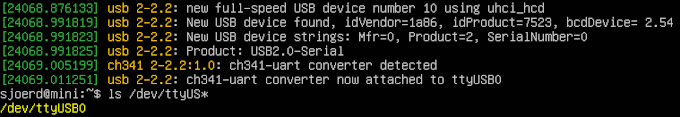
Linux
The device is called something like /dev/ttyUSB0. If you plug the device in a look in the logs (sudo dmesg), a line typically indicates where the newly found device is attached:
macOS
The device is called something like /dev/tty.wchusbserial1410. I haven’t found a reliable way to get the filename of this port. You can try the following things:
- View the logs using
sudo dmesg. - List USB devices using
ioreg -p IOUSB, or by going to About This Mac, System Report, USB.
If all else fails, list all files in /dev, plug the device in, list again and diff the two:
$ ls /dev > before.txt
$ ls /dev > after.txt
$ diff before.txt after.txt
268a269,270
> cu.usbserial-1410
> cu.wchusbserial1410
444a447,448
> tty.usbserial-1410
> tty.wchusbserial1410
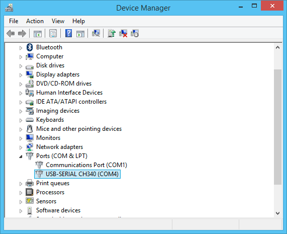
Windows
On Windows, the port is called COM3 or some other number. You can find the correct port number in the device manager.
Talking to the serial port
You need software that sets the baud rate and sends and receives bytes over the serial port. Use tio on Linux, Putty on Windows and Serial on macOS. Don’t use screen.
When using Putty on Windows, turn of software handshaking, which is on by default. In the Serial menu, set Flow control to None.
You typically want software that supports arbitrary baud rates and informs you of what is going on. In that regard, screen and gtkterm are insufficient. While screen can set up a serial connection and it may works correctly, it doesn’t inform you when it can’t do what you want. If you run the command screen /dev/ttyUSB0 128000, you may expect the baud rate to be set to 128000. However, this is an unsupported baud rate and screen silently falls back to 9600. Everything seems to be OK, except the baud rate is incorrect.
Even more weirdly, screen /dev/ttyUSB0 4098 uses a baud rate of 115200, because the kernel constant B115200 equals 4098, and screen interprets the given number either way.
The cu command at least tells you that the baud rate is unsupported.
Everything you type is sent over the serial line, which can make it tricky to exit the program. Use the following key shortcuts to exit:
- screen: ctrl-a, k, y
- tio: ctrl-t, q
- cu: ~. enter
Finding an UART interface on a device
If you want to connect to an embedded device, the first step is to find the correct pins on the board. Often there is a row of four or five pins with at least ground, Vcc, Rx and Tx. Sometimes the pins are omitted and there are only holes. Often such a connection is labeled as J5 or another number.
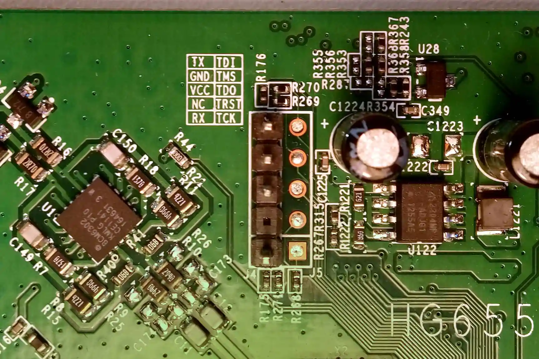
In the following image you can see a UART interface on a Huawei modem. The device came with blank pads and I soldered the pins to it. You can see a little table in the silk screening that describes the pins: Tx, Gnd, Vcc, Rx. The pins on the right side are JTAG pins. Having UART and JTAG in one connector makes it possible to easily connect a debug cable to the board for debugging. For similar reasons, debug ports are often on the side of the board.
If you suspect a pin to be a UART line, the first step is to measure the voltage using a multimeter. First, find a good connection for the common ground and connect the black lead of the multimeter to it. Then measure the voltage on the suspected pins with the red lead. A Tx line will be 3.3V when idle. Keep measuring while rebooting the device. Data is often sent on boot, so we can use this to determine whether data is sent over the line. If data is sent, the voltage will temporarily drop below 3V according to the multimeter.
Now you have determined that the line has an acceptable voltage and there is activity on it. This does not yet mean that the line is an UART line, it could use another protocol such as I2C or SPI. One way to determine this is to use a logic analyzer or oscilloscope to view the electrical signals. Or, you can connect your USB to UART bridge and see if it works.
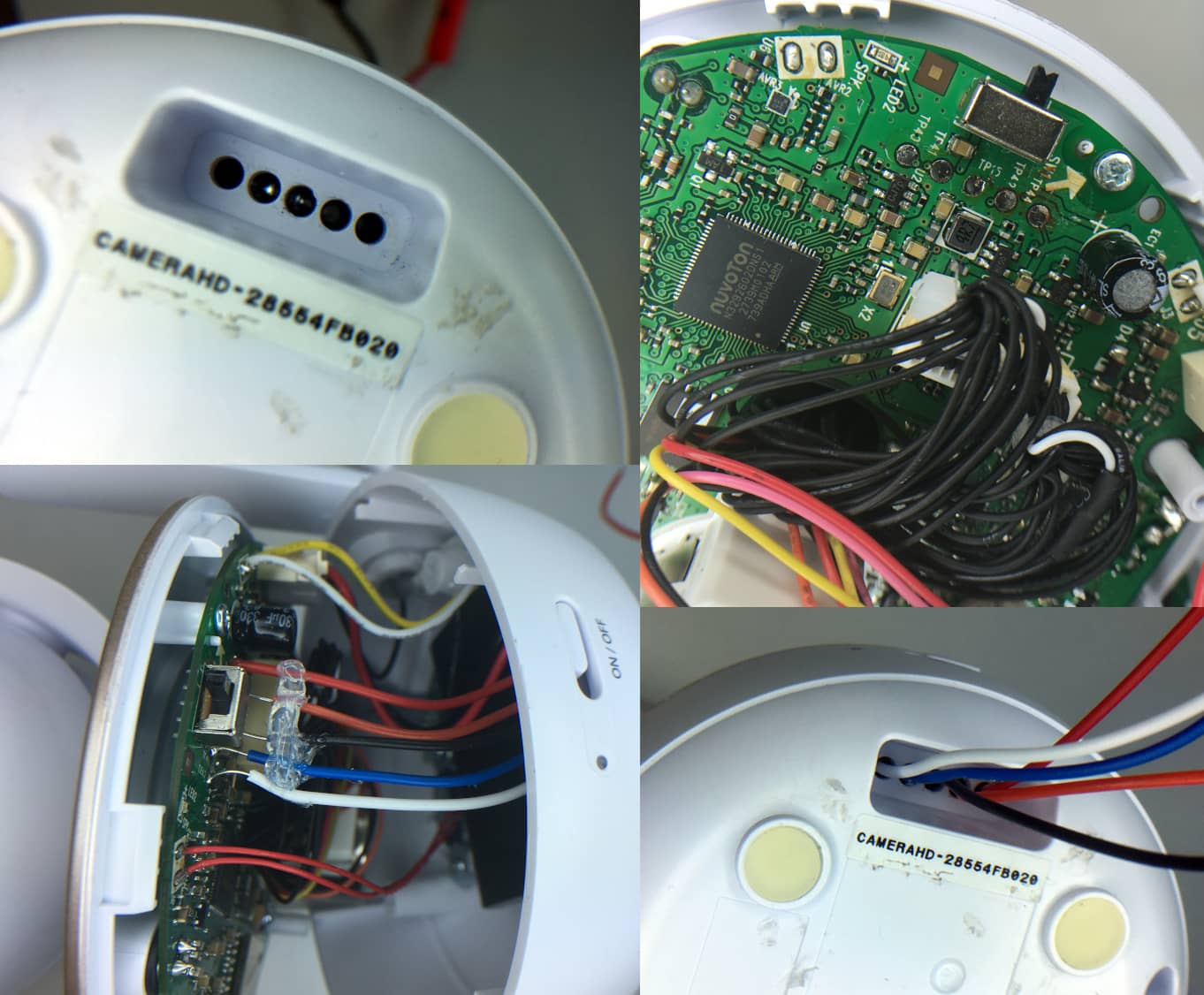
In the example below a camera has five holes, initially hidden under a white sticker. This makes it possible to access the UART interface from the outside. However, I couldn’t get this working and soldered wires to the pads. The pads are marked as TP41, TP42, and so on, where TP stands for test point.
Connecting to the device
Before connecting to the device, make sure it emits a voltage that is compatible with your bridge. RS232 lines, for example, use -15 and +15V, which can easily ruin your brige. Even if the voltage is acceptable, you may want to put a 300Ω resistor between your bridge and the device to prevent too large currents.
When connecting your UART bridge to the device, connect ground, Tx and Rx. The Rx of the bridge connects to the Tx of the device, and the other way around.
Whether to connect Vcc depends on whether you use an isolated bridge. If you have an isolated bridge there is no electrical connection between your USB port and the I/O pins. However, the I/O pins still need to put out a voltage, and for this the I/O side needs Vcc.
If your adapter is not isolated, connecting Vcc of your bridge to the device may interfere with the voltage already on the device. If the device gets power from another power supply it already has a certain voltage level on its Vcc pin. If you connect the bridge’s Vcc pin and the voltage is different, a current will flow which may damage the device.
An alternative is to disconnect the device from the power supply and supply power through the USB to UART bridge. However, most bridges can only supply up to 100 mA or so, which is not enough for most devices.
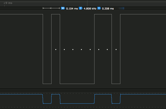
Finding the baud rate
A common way is to try the standard baud rates until the output looks legible. Alternatively, the baud rate can be determined by measuring the length of the shortest pulse. With a baud rate of 9600, one bit takes 1∕9600 of a second. So if we measure the duration of one bit we can determine the baud rate.
This is easiest with a logic analyzer, which just shows the timing in the interface:
Alternatively, it is possible with a microcontroller by using input capture to measure pulse widths. I created an autobaud program that works on Arduino Uno and can determine baud rates up to 200,000 bps reliably.
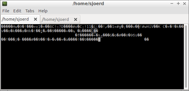
Using an incorrect baud rate will typically show gibberish, although it is also possible that you see nothing at all.
Troubleshooting
The first step is to pinpoint where the problem is: is it between your computer and the bridge or between the bridge and the device you want to connect to?
Locating the problem
- Does your computer get an extra COM or tty device when plugging the bridge in? If not, you have a driver problem.
- Check the LEDs on the bridge.
- Is the Tx LED lighting up when you are sending data? Then the connection between your computer and the bridge is OK.
- Is the Rx LED lighting up but you don’t see anything in your terminal application? Then the the connection between the bridge and the device is OK and the problem is between your computer and the bridge.
- Disconnect the bridge from the device and connect the Rx and Tx of the bridge together. Is your typing reflected in the terminal? Then the connection to the bridge is OK.
USB problems
- Check whether your operating system recognizes the USB device.
- On Linux: lsusb
- On macOS: ioreg -p IOUSB
- On Windows: check device manager.
- View the logs (using dmesg) when putting the device into your computer.
- Unplug the bridge, list all devices (ls /dev), plug the bridge in again, and compare the two.
- Try another known good USB cable.
- Retry what you are doing a couple of times, to rule out a temporary problem.
Remote problems
- Is the baud rate correct?
- Is the bridge using the baud rate you think it is?
- Does the device use an inverted data line?
- Does the device need to have serial communication enabled? Does it have a data request line?
- Is ground correctly connected to the device?
Conclusion
Using a USB to UART bridge can be pretty simple if it works, or it can be painful if it doesn’t. I am surprised that there is so much to tell about UART’s.
Read more
Chips
- ASIX MCS7810
- Atmel ATMEGA8U2 or 16U2 with Arduino USBSerial Firmware
- Cypress CY7C65211 or CY7C65213
- Microchip MCP2200
- Prolific PL2303HX
- Silicon Labs CP210x
- Texas Instruments TUSB3410
- WCH-IC CH340
Isolated adapters
- DUPPA Debug Board
- Microchip MCP2200
- MikroElektronika USB UART 2 Click
- Silicon Labs Isolated USB Evaluation Kit
- Sunrom 1435 USB - UART Isolated Converter Industrial Grade
- UC-3100P Isolated USB to UART TTL converter
- ZeptoBit Optically Isolated USB-UART Adapter
- µArt
Articles
- Reverse Engineering Serial Ports
- Buggy CP2102N Replaced
- Using the Hardware Serial Ports
- How high of a baud rate can I go (without errors)?
- Review: CP2102N USB-UART Bridge
- Linux-custom-baud-rate
- Setting Arbitrary Baud Rates On Linux
- FTDI FT232RL: real vs fake
- µArt by Karoly Pados
- CH340, CH341 USB to RS-232 chip compatibility
- The Advantages of Galvanic Isolation
Tweets
- @az6667: i don’t have a fast enough UART
- @TubeTimeUS: j10 looks like a UART header
- @KristinPaget: don’t buy FT232 - the onboard 3v3 regulator can only supply 50mA
- @hamityanik: I think there is an issue with CP2102N MacOS drivers
- @stefandz: Just found a second error in the @siliconlabs CP2102N datasheet
- @protosphere_: PL2303 is so flaky I want to flip a table